Pate's PiKon telescope - Blog
NOTE! I decided to order this blog starting from the oldest posts at the top. I usually write my blogs for my various projects in the order where the latest posts are at the top, but as this project should actually get finished at some point, I think it makes more sense to read this as a sort of a diary, from start to finish.
June 23rd, 2017 - The Beginning
Yesterday evening I pretty much accidentally ran across an interesting YouTube video describing a telescope built around a Raspberry Pi (with it's camera) using mainly 3D-printed parts. This was quite interesting to me, as I have been interested in astrophotography, but had not wanted to spend a lot of money for the necessary equipment.
Last winter I had purchased a cheap (35 euros!) 60x telescope from our local Lidl store, and 3D-printed a Phonescoping holder for my cell phone to try to take images of the Moon and Venus. The results were less than satisfactory, though.
However, for this PiKon telescope I would only need the mirror and the tube (and some minor additional parts), as I already had a Raspberry Pi 2 computer and a Raspberry Pi camera left over from my original Piro robot project. I had purchased a new Raspberry Pi 3 and the latest 8 megapixel camera for my new Piro2 robot. I also have a 3D-printer, so I can print all the 3D-printed parts myself. The PiKon parts list also include a 10cm piece of a T2.5 belt, but I had some belt left over from when I built my 3D printer, so I would not need that one either.
This morning I then sent an inquiry to the people at https://pikonic.com/ about the possibility of purchasing a custom collection of parts. They replied quite fast and confirmed that a custom collection of parts is very much possible, and quoted me a price for the parts I asked for. Thus, I ordered the parts I thought I needed.
June 26th, 2017 - Printed the First 3D Parts
After I made the order, I started working on the 3D printed parts for the telescope. I downloaded the STL files and build instructions from the PiKon DropBox location. I started with the two parts that hold the mirror, the MirrorBase.stl and MirroMount.stl. Both got printed pretty well, the base had slight warpage along a part of the edge, as my printing bed seems not to be exactly uniformly level. I think this should not cause any problems, though, as the mirror can be adjusted using the collimation screws, and that should take care of any issues with the printed parts.
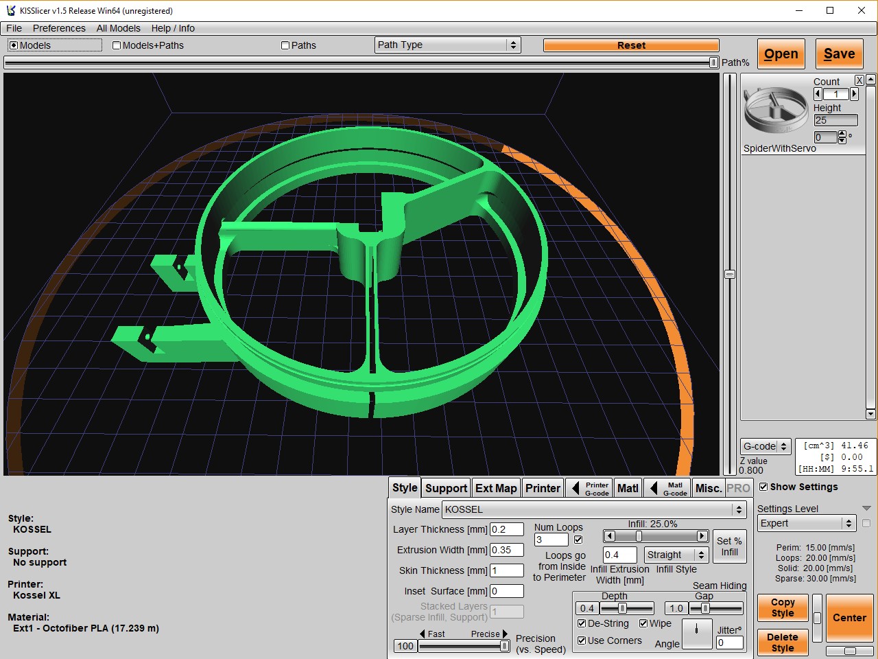
June 29th, 2017 - Spider with Servo
My plan is to make this telescope fully motorized and remote-controlled, so that I can just take the telescope outside during cold and clear winter nights, and then go back inside and sit on my computer commanding the telescope and taking pictures. In addition to controlling the direction where the telescope points to, I also wanted to control the focus of the telescope remotely. Thus, I decided to modify the "spider" part of the telescope to have a mounting point for an SG90 micro servo that would turn the focus knob.
As I did not yet know how much movement the focus rack needs, and how accurately it needs to be positioned for a good focus, I decided to make the mount so that I can attach the servo in either orientation (the servo axle can either be closer or farther from the focus pulley rod). I could then later (after I had tested the telescope) decide on the proper gearing between the servo and the focus pulley rod. After adding this servo mount to the spider, I printed it as well.
June 30th, 2017 - Pulley for my GT2 Belt
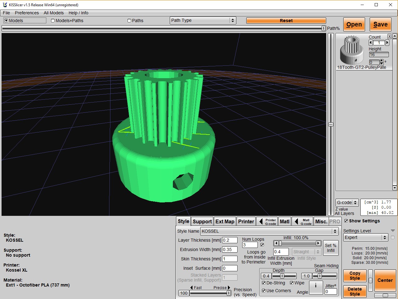
Oops, yesterday I realized I had made a bit of a mistake when I ordered the PiKon package. I had not checked the type of the belt I had left over from building my 3D printer, I had just assumed it was of the same T2.5 type that the PiKon telescope uses for the camera focus rack system. It turned out that my belt is of the GT2 type, not of the T2.5 type. I assume those numbers are related to the pitch of the teeth, so quite probably the T2.5 pulley included with the PiKon package won't work properly with my GT2 belt.
I thought about contacting the PiKon people again and ordering the T2.5 belt separately, but then I began wondering whether it would be possible to just 3D-print a GT2 pulley instead. If I manage to print one, I should then be able to use my GT2 belt without issues. I started searching ThingiVerse for ready-made GT2 pulleys, and found one that seemed to be just what I needed: 18 Tooth GT2 Pulley by OoiTY. I printed that, but noticed that the teeth were rather shallow, and it did not seem to have a very good grip against my GT2 belt. This may have been caused by some issues with my 3D printer, or the settings I used when slicing te object. However, I decided to modify the object slightly, making the teeth deeper, and then printed the object again. This seemed to work fine, and the pulley seemed to have a good grip against my GT2 belt.
July 2nd, 2017 - Designing the Mount
Now I had printed pretty much all the main parts for the telescope, so I began figuring out the type of the mount I am going to put it on. There are two main types of telescope mounts, the simpler altitude/azimuth mounts, and equatorial mounts. The latter has an axle that points to the North Star, and thus it can rotate this axle at the speed of one full rotation per day to counter the rotation of the Earth. This is pretty important for astrophotography, to keep the starts still for long exposure pictures. The simpler altitude/azimuth mount just allows you to set the compass direction and altitude in degrees from horizontal.
I have two 400rpm at 12V (and 200rpm at 6V) geared motors left over from my original Piro robot, and I plan to use these to drive the telescope mount. To reach the one-rotation-per-day speed the motor should run at 1/1440 rpm, and thus I would need a 1:288000 gearing for the 6 volt speed of my motor. That sounds a bit excessive, so I am thinking that I will start with an altitude/azimuth mount, and then perhaps later either modify my mount to be equatorial, or build a separate equatorial platform to counter the rotation of the Earth.
For the altitude/azimuth mount, the "slewing" (when the telescope is moving towards the target orientation) speed would be nice to be around 90 degrees at 15 seconds, so that I don't need to wait a long time for the telescope to move. That would mean 360 degrees per minute, or 1 rpm. So, for the 400rpm max speed of my motors, a 1:400 gear reduction would be perfect.
I needed a way to count the revolutions of my motor, so I ordered a set of two rotational speed measuring modules from dx.com. These should allow me to measure how fast the motor is rotating, and thus how many degrees the telescope has turned, when I know the gear ratio.
July 3rd, 2017 - Wooden Worm Gear
When trying to figure out how to build the 1:400 gearing, I decided to go with a worm drive. It is very simple to calculate the gear reduction ratio for worm drives, as the ratio is directly the number of teeth in the worm gear. Thus, for my 1:400 gear reduction ratio, I would need a 400-tooth worm gear.
I started by modeling the worm part of the worm drive using my Cinema 4D software (using Sweep object containing a Spline and a Helix), and then attempted to 3D-print it. This did not work very well, though. The worm has such deep overhangs that I would have needed to use support material, which however would make the surface of the worm quite rough. I doubted I could smoothen the worm sufficiently for it to turn smoothly against the gear.
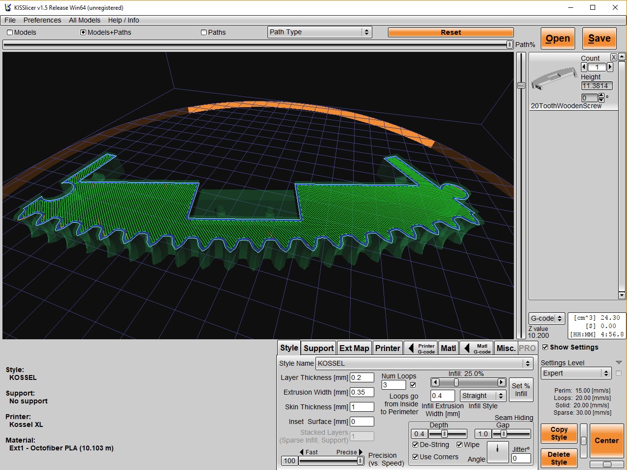
I happened to find an old wooden clamp from my tool shed, and decided to repurpose that for my worm drive needs. The wooden screw of the clamp was about 20cm long, so I thought I could cut this into several worms, each around 5cm long, and then just 3D-print the large gear (in several parts, obviously). This wooden screw had longer pitch than what I originally planned to use, so I decided to drop to 1:200 gear ratio (and thus to a 200-tooth gear) instead. This will make the telescope slew twice as fast as I originally planned, but I can of course simply give lower voltage to the motors to make them run slower.
I measured and modeled the wooden screw, and then based on this model, I modeled a 20-tooth piece of the worm gear. Joining 10 of these would create a full circle with 200 teeth, for the 1:200 gear reduction ratio. The radius of the worm gear turned out to be 27.7 cm, which seemed fine. The whole gear is a few centimeters short of 60cm, which should not look out of place alongside the telescope tube that is 63cm long. I printed one such section, to make sure my measurements were correct. It seemed to grip the wooden screw quite nicely.
July 5th, 2017 - Cell Tower Trigonometry
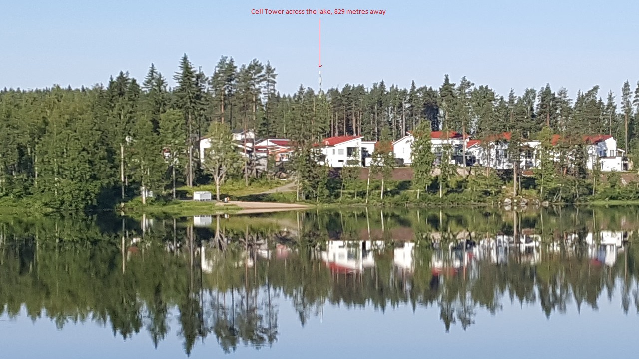
There is a cell tower visible from my back yard across the lake I live by. I decided that I will use that tower as a landmark when eventually calibrating my telescope. If I know the exact direction of that tower relative to where I will put my telescope on my back yard, I should be able to easily calibrate the altitude and azimuth of my telescope at the beginning of each viewing session. Thus, I decided to see if I could determine the exact location of that cell tower.
I used Google Street View to find the cell tower, and then used Google Maps and it's distance measuring feature to determine that the tower is exactly 829 metres away from the table on my back yard. I then used some trigonometry to determine that the tower is at compass direction 253,53 (that is, a bit South of West) from my back yard. I am not quite sure how tall the tower is, but I think I don't actually need that info, as I can certainly use some other method to calibrate the altitude angle of my telescope.
July 6th, 2017 - PiKon Package Arrives!
Today a courier brought the PiKon package I ordered! I opened the package, and noticed that it contained both the T2.5 pulley and the T2.5 belt (even though I had not ordered the belt). So I would not have needed to print the GT2 pulley myself. However, since I had already glued the GT2 belt to the CameraHolder part to work as the focus rack, I decided to use my printed GT2 pulley anyways.
However, the package did not contain the longer Raspberry Pi camera cable that the telescope would need, and I realized I had forgotten to order that when I made my custom order! Stupid me... Ordering that all the way from UK would cost a lot in postage and take many days, so I decided to check if some local store would carry such cables. I visited an electronics store in my local town, but they did not have such, so I decided to look for online stores. I found several that would have those cables in stock, and decided to go with Robomaa, as I had not encountered that store before, and they seemed to carry all sorts of interesting robotics stuff. I would need to check them again when I continue my robotics projects. The cable is 30cm long and has a part number ADA-1648. I also ran into a problem with the spider I had printed. It did not fit inside the tube! I measured that the tube inner diameter was 12.5 cm, but the STL file of the spider had the spider measuring 12.6 cm!
However, even though my camera cable was much too short, I could not attach the spider properly, and the tube inside was still white, I wanted to check if I would get some kind of an image. I used duct tape to hold the parts somewhat together, and let the Raspberry Pi pretty much hang from the camera cable and some duct tape, pointed the telescope out of my window, and tried to get an image. Here below is the picture I managed to take. It was not much in the way of quality, but it proved that in principle my telescope works, so I was pretty happy.

July 7th, 2017 - Reprint of SpiderWithServo
Today I adjusted the SpiderWithServo STL file to be 1 mm smaller in diameter (as my 3D printer seems to always print just slightly larger than the model measurements), so it should still be a tight fit. Several hours of printing later, I tested the new spider, and it fit just snuggly into the tube. It was curious how the mirror base fit perfectly using the original measurements, but I think that might have been caused by the slight warping that I encountered when printing that part.
I also painted the inside of the telescope tube black at both ends. I decided that I will glue some black fabric I had left over (from my home theatre building project) to the inside of the tube, as I thought this would reflect even less light than simply painting the tube black. I don't know whether this is a good idea, but we shall see. This meant that I do not need to paint all of the inside of the tube black, just the ends.
I have also decided on the type of bearings to use for the altitude axle. I was in a hardware store looking for ideas, and ran into a special sale of fidget spinners. I realized that these have pretty good bearings, and they don't cost much, so I purchased a couple of them. At home I found out that they have very nice ceramic bearings in the middle, and each of the ones I purchased had three additional lower quality bearings. So from each spinner I got four usable bearings, which was a pretty good deal. I began designing the telescope mount around these bearings.
July 10th, 2017 - 3D-printing more parts
During the previous couple of days I have been printing some more parts for my telescope. I measured, modeled and printed the part that attaches the telescope tube to the altitude axle bearings (I called this TelescopeCollar). I had some issues with my printer during the print, the circular bed got a bit loose and started rotating. I noticed this pretty quickly and rotated it back, but it still created an unaligned layer into the print. However, since the print took quite a few hours and consumed a lot of filament, I decided not to reprint the part. It should still work fine.
I also have a different case for my Raspberry Pi than what the original RaspberryPiMount was designed for, so I adjusted the mount for the measurements of my case. I printed that, and also printed the two feet for the RaspberryPiMount. I glued the feet to the mount, but did not yet attach the mount to the teleascope, as I am still waiting for the longer camera cable to arrive. The PiKon instructions state that it is best to test the telescope first, before attaching anything permanently, and I plan to follow that suggestion.
July 11th, 2017 - Longer Camera Cable Arrives, First Tests!
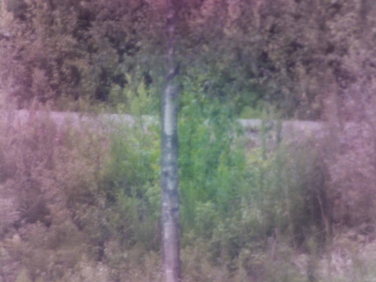
Okay, today the longer camera cable arrived! I could now attach the Raspberry Pi to the RaspberryPiMount, and attach that at least semi-properly to the telescope tube. I had also managed to glue the black fabric on the inside of the telescope tube, so I should get much better contrast images. I again pointed the telescope through my window across the lake towards the trees there, and began attempting to find the proper focus. For some peculiar reason the color looks pretty strange, like the green channel would only be active in the middle of the image, and the image gets redder towards the edges. I am using the newer 8 megapixel Raspberry Pi camera V2, so it may be that it has some firmware color adjustments that try to compensate for the color aberrations of the original lens. As the telescope uses the camera with the lens removed, this color compensation will actually misadjust the colors. Or perhaps my mirror is not collimated properly, although I am not sure how that could cause such color issues? Or perhaps the fact that this is a spherical mirror instead of a paraboloidal mirror causes the color issues?
July 12th, 2017 - Motorized focus work
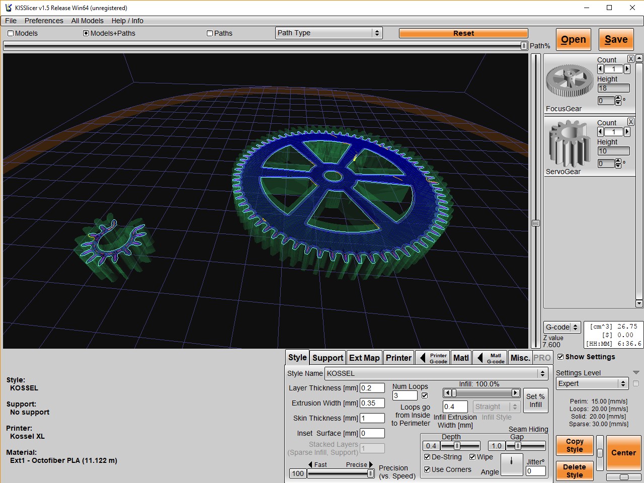
As I had a lot of trouble focusing the image manually yesterday, I realized that I need to build the motorized focus system sooner rather than later. It seemed that the focus changed quite a bit even with very small changes to the focus rack, so I decided to have the biggest gear ratio I could fit to my focus servo mount. I used the Cinema 4D CogWheel spline tool to design the gears, and then modified the smaller servo gear to nicely attach to the servo arm.
July 14th, 2017 - PiKon Control Software Work
For the past two days I have been working on a simple web-based control software for my telescope. I want to be able to control it using a web interface, so that I can use my iPad when performing the initial calibrations, and then continue using it from my Windows PC, where I can also run the Stellarium planetarium software. I found a Simple Multi-threaded web server written in C using pthreads example code, and used that as the basis for my control software. I had already learned how to programmatically control the Raspberry Pi camera when I coded the software for my Piro robot, so I also pretty much just copied that code over. Also the servo control is based on the code I had in my Piro robot, based on the pigpio library.
Currently my simple control software can control the focus servo, and it can also take a snapshot picture with various zoom levels. The zoom levels actually just tell how much of the original 8 megapixel picture is resized to the 640x480 preview image shown on the page. I also attached an ADXL345 triple axis acceleration module to my Raspberry Pi. That was left over from my Piro robot, as I had first purchased that, until I realized that I also need a gyroscope for a balancing robot. This part only has the accelerometer, so it was not useful for my balancing robot. It has a resolution of around a degree when it is used for measuring elevation angles, so it is not sufficient to aim the telescope, but it gives a reasonably accurate calibration starting point, at least.
July 15th, 2017 - First Proper Images!
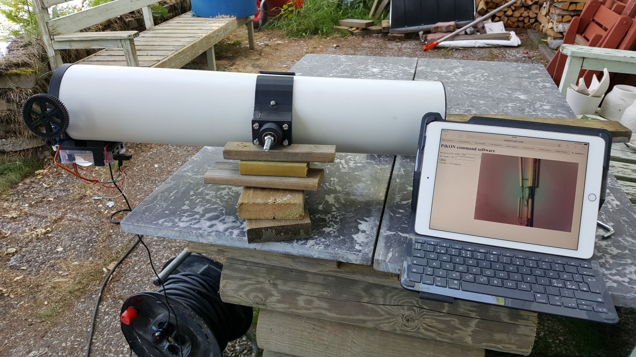
Today was a nice sunny morning, so I took my telescope and iPad outside, and began experimenting with my new control software. Here below is a picture of the current setup. The telescope is just sitting on top of some wooden blocks, and is very prone to shaking in wind gusts. The picture also shows the motorized focus system, and the control software is open on the Safari browser on my iPad.
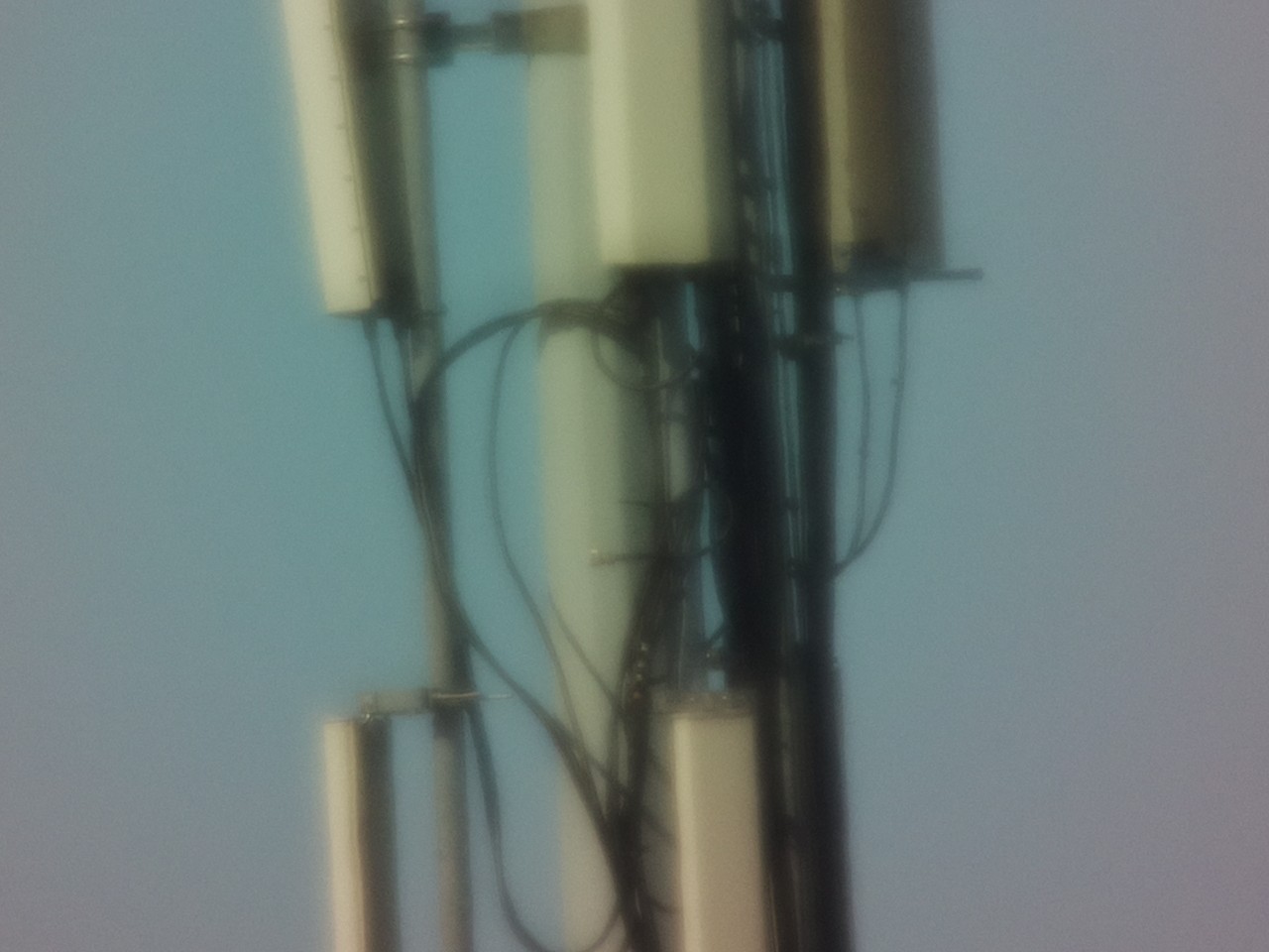
It took me a while to find the cell tower, but I finally managed to point the telescope towards it, and then was able to take a picture of it. Here below is the middle part of the original 8 megapixel JPG image cropped to 1280x960 (so it does not get resized, unless you view it on a very small screen). I was pretty happy with this picture, as you can pretty much see the bolts and all the wiring quite clearly from 829 meters away. It was a sunny morning and the picture was taken across a lake, so there is a lot of air turbulence affecting the picture as well. Also, I did not adjust the default JPG compression level, or do any other adjustments to the picture.
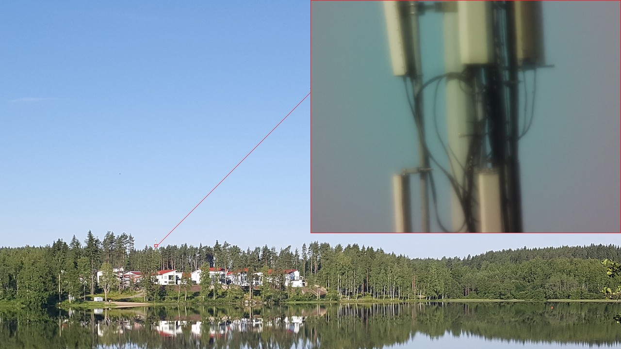
Here below is a picture-in-picture image, showing the view across the lake taken with my cell phone camera, resized 2:1, and then cropped to 1280x720, with the telescope image of the cell tower also resized 2:1 and then cropped to 640x480 and pasted into the image. This pretty clearly illustrates the amount of magnification I can get from this quite cheap 4.5" telescope. I was pretty happy with the quality of my PiKon telescope, it should be able to get good pictures of the moon and hopefully also of Jupiter and Saturn, when the winter comes.
July 17th, 2017 - Stellarium Telescope Protocol, 3D printer issues
I have seen YouTube videos of people using Stellarium to control their motorized telescopes, and I wanted to do something similar with my telescope. I thought that it would be much more convenient to just point-and-click in Stellarium, as opposed to checking the coordinates there, and then separately inputting them to my control software.
Yesterday I began studying the communications protocol that Stellarium uses to control a telescope. I found a description of the protocol together with some example c++ code to implement the protocol. I am using plain C instead of C++ for all my Raspberry Pi programming, so I will need to convert the code while implementing it for my telescope.
That example code did not include any calculations from the Right Ascension / Declination coordinate system to Altitude / Azimuth coordinate system, which I would also need, so I also hunted for examples and algorithms to help me with that. I found a thorough explanation titled Converting RA and DEC to ALT and AZ from the Stargazing.net pages. I also found another Motorizing a Telescope project, that had code for CelestialCalculations. This one was written in C#, so it also required conversion to C, but luckily I am fluent also in c# so that would not be a problem.
I have also encountered some issues with my 3D printer. I tried to print the large middle part of the altitude gear, but used too low infill ratio, which caused the part to begin warping at the edges. This in turn caused the extruder head to begin hitting the parts of the previous layer that had started to curl up, which eventually caused one of the stepper motors to skip, which then caused the print to fail. When I tried to restart the print after using a larger infill, I noticed that the calibration was way off. Then I noticed that one of the belts was no longer tight, several bolts had gotten loose, one of the 3D printed parts of the printer itself had broken, etc.
It took me a while to get the printer working again. I had to temporarily fix the broken part, so that I could print a replacement part (this is a neat thing with 3D printers, they can practically repair themselves!). After replacing the broken part with the new replacement, and recalibrating the printer, it finally began to work properly again. However, I decided to simplify the center part of the altitude gear wheel, and also make it much thinner so it would not take so many hours and so much filament to print.
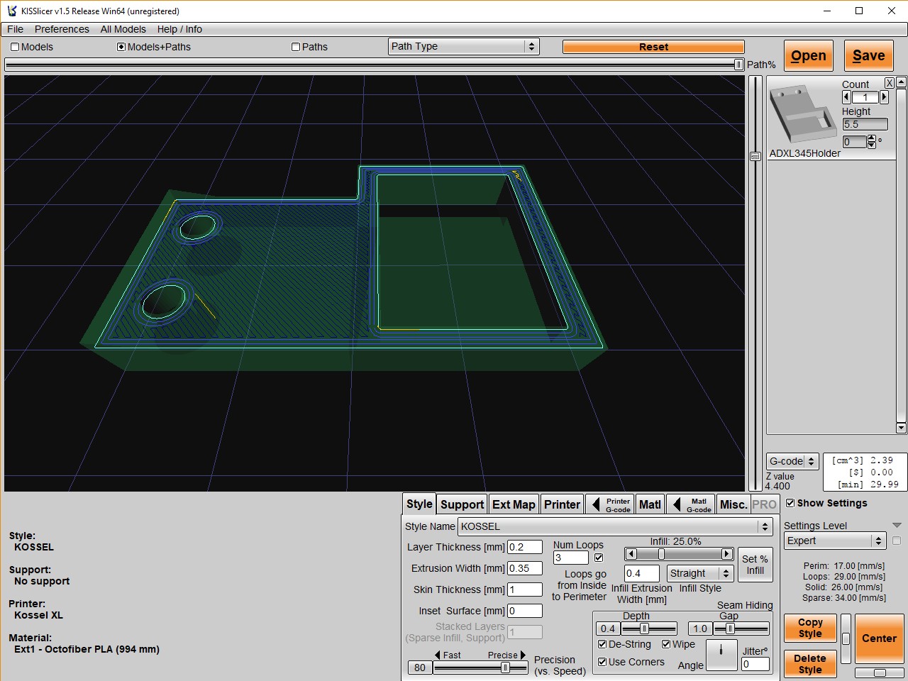
July 18th, 2017 - 3D Printing a Holder for the ADXL345 Accelerometer
Until now my ADXL345 accelerometer had just been attached with a rubber band on top of the Raspberry Pi itself. Today I decided to 3D-print a proper attachment holder for it. I decided to design it so, that I can screw it to the side of the Raspberry Pi holder. This was a simple part that was fast to print, and made the telescope look somewhat cleaner.
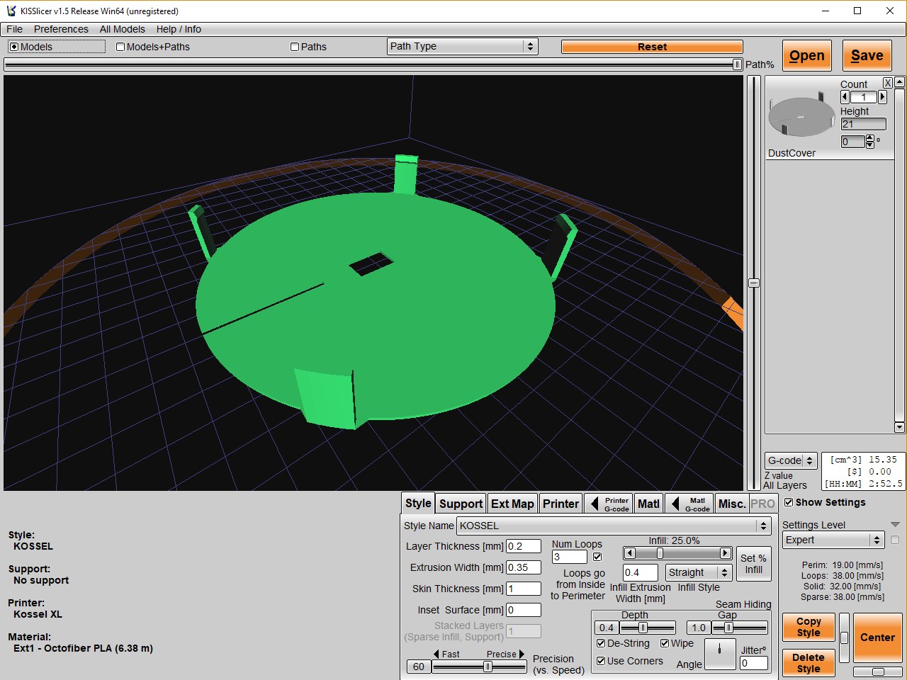
July 19th, 2017 - Dust Cover
I began to worry that my telescope (either the mirror, or more seriously, the exposed camera sensor) would collect dust while I work on the software and mount, so I decided to design and print a dust cover for my telescope. This was pretty easy to do, as I could use the spider object as a basis for all the measurements.
I also began figuring out how to drill a hole into the wooden screw at the exact center. It seems the best way would be to attach the wooden screw itself to a drill, and use a stationary drill bit, but my drills only have an aperture of about 10 mm, while the wooden screw has a diameter of 29 mm. I perhaps need to print some kind of an attachment part for that. I just don't know if a 3D-printed part would be strong enough for such a purpose.
July 20th, 2017 - Stellarium Communications Work
I worked several hours today with the Stellarium communications, and managed to get the data going in both directions! The actual communications code was not all that difficult to get working, as I could pretty much use the original C++ code, just converting it to plain C where needed. However, the celestial calculations were a bit trickier. I first tried to use that C# example code, but ran into various problems, so I decided to forget that code, instead write my code simply based on the description at the Stargazing.net site. Using that (and some additional info from Yahoo), I managed to get the code working, and displaying the same altitude and azimuth values that Stellarium shows, when receiving the RA and Decl values that Stellarium sends via the protocol. I did not yet have any hardware to handle the turning of the telescope, so I just had to print out the values in my Rapsberry Pi code. Here below are the celestial calculations (from Ra/Decl to Alt/Az, and vice versa) I came up with in my code.
    #include "pikon.h"
    #include <sys/time.h>
    #include <math.h>

    // Return the current UTC time in microseconds (since Unix Epoch = 1970)
    long long int GetNow()
    {
        struct timeval tv;
        gettimeofday(&tv, 0);
        return tv.tv_sec * 1000000LL + tv.tv_usec;
    }

    // https://answers.yahoo.com/question/index?qid=20080630193348AAh4zNZ
    double CalculateLocalSiderealDegrees(double longitude, long long int utcNow)
    {
        double D = (utcNow - 946728000LL * 1000000LL) / (1000000.0*60.0*60.0*24.0);
        return fmod(280.461+360.98564737 * D + longitude, 360.0);
    }

    // http://www.stargazing.net/kepler/altaz.html
    void ComputeAltAzimuth(long long int utcNow, double longitudeDegrees, double latitudeDegrees, double rightAscentionHours, double declinationDegrees,
                           double *azimuthDegrees, double *altitudeDegrees)
    {
        double localSiderealDegrees = CalculateLocalSiderealDegrees(longitudeDegrees, utcNow);
        double rightAscentionDegrees = rightAscentionHours * 15.0;	// Convert hours to degrees by multiplying with 15
        double hourAngleDegrees = localSiderealDegrees - rightAscentionDegrees;
        if (hourAngleDegrees < 0.0)
            hourAngleDegrees += 360.0;
        double hourAngleRadians = 2.0 * M_PI / 360.0 * hourAngleDegrees;
        double declinationRadians = 2.0 * M_PI / 360.0 * declinationDegrees;
        double latitudeRadians = 2.0 * M_PI / 360.0 * latitudeDegrees;

        double altitudeRadians = asin(sin(declinationRadians) * sin(latitudeRadians) + cos(declinationRadians) * cos(latitudeRadians) * cos(hourAngleRadians));
        double azimuthRadians = acos((sin(declinationRadians) - sin(altitudeRadians) * sin(latitudeRadians)) / (cos(altitudeRadians) * cos(latitudeRadians)));

        *altitudeDegrees = 360.0 / (2 * M_PI) * altitudeRadians;
        *azimuthDegrees = 360.0 / (2 * M_PI) * azimuthRadians;

        if (sin(hourAngleRadians) > 0)
        {
            *azimuthDegrees = 360.0 - *azimuthDegrees;
        }
    }

    void ComputeRaDec(long long int utcNow, double longitudeDegrees, double latitudeDegrees, double azimuthDegrees, double altitudeDegrees,
                      double *rightAscentionHours, double *declinationDegrees)
    {
        double localSiderealDegrees = CalculateLocalSiderealDegrees(longitudeDegrees, utcNow);
        double latitudeRadians = 2.0 * M_PI / 360.0 * latitudeDegrees;
        double altitudeRadians = 2.0 * M_PI / 360.0 * altitudeDegrees;
        double azimuthRadians = 2.0 * M_PI / 360.0 * azimuthDegrees;
        double declinationRadians = asin(sin(latitudeRadians) * sin(altitudeRadians) + cos(latitudeRadians) * cos(altitudeRadians) * cos(azimuthRadians));
        double hourAngleRadians = acos((sin(altitudeRadians) - sin(declinationRadians) * sin(latitudeRadians))/(cos(declinationRadians) * cos(latitudeRadians)));
        double hourAngleDegrees = 360.0 / (2.0 * M_PI) * hourAngleRadians;
        double rightAscentionDegrees = localSiderealDegrees - hourAngleDegrees;
        if (rightAscentionDegrees < 0.0)
            rightAscentionDegrees += 360.0;
        *rightAscentionHours = rightAscentionDegrees / 15.0;
        *declinationDegrees = 360.0 / (2.0 * M_PI) * declinationRadians;
    }
July 21st, 2017 - Encoders Arrived!
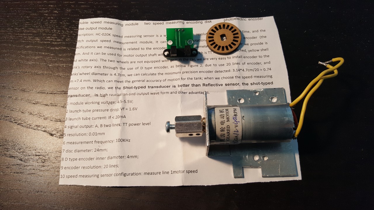
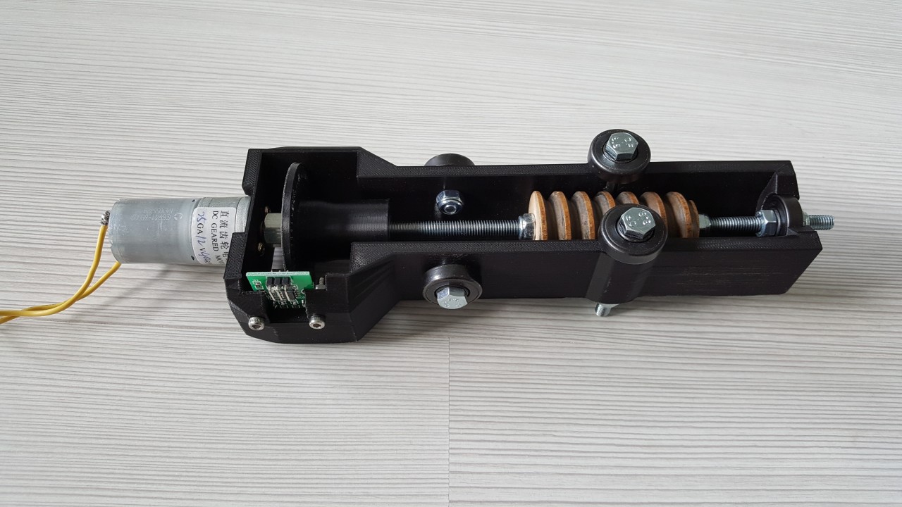
Okay, today the rotational speed encoders I ordered on the 2nd of this month from DX.COM (in China) arrived. Great, now I can proceed with actually motorizing my telescope! The encoders came with 26mm diameter 3mm thick wheels that had 20 holes, so they would cause 20 signals per a full revolution. However, the axle slot of the encoder wheels was not suitable for my purposes, as my motors had a 4mm axle, and I also had some 12mm hex adapters for my motors that I would like to use to attach the motors to the encoder wheels. The image below shows the encoder and the encoder wheel, together with my 400rpm motor with the 12mm hex adapter, on top of the instructions leaflet that came with the encoders. The leaflet was cut a bit strangely, cutting out the beginning of each line of the text. The most important data was intact, though.
Instead of trying to use the included encoder wheels, I thought I could just 3D-print new wheels that would suit my needs better. I decided to go with slightly bigger wheel. I calculated that if I would go with a 50-slot wheel, the encoder wheel diameter would by exactly 50 mm, which sounded nice. With a 50-slot wheel running at a maximum speed of 400 rpm, I would get 20.000 signals per second, which is suitably below the 100 kHz maximum limit of the encoder. Even if the max limit is calculated from both on and off signals, it would still be less than half of that. I also calculated that with this 50-slot encoder wheel, I can get an altitude angle resolution of 360 / 200 (the number of teeth in the worm gear) / 50 (the number of slots in the encoder wheel) = 0.036 degrees. As the field of view of the telescope is supposed to be about 1/4 = 0.25 degrees, the resolution of the altitude angle should be sufficient to point my telescope pretty accurately towards a celestial object.
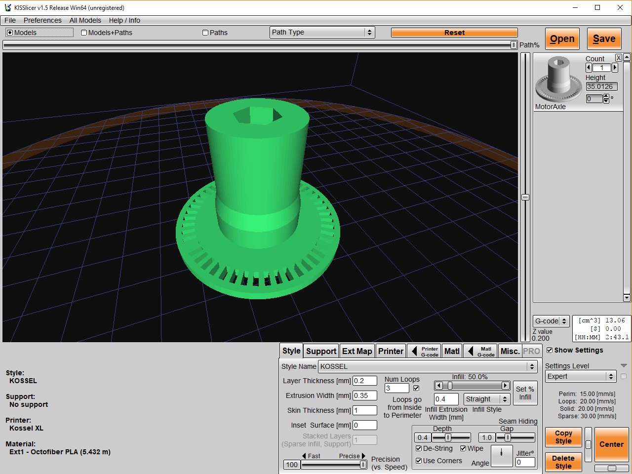
Thus, I designed and 3D-printed a new encoder wheel (calling it MotorAxle, as it will attach to the motor adapter at one end, and to some bolts on the 6mm threaded rod I plan to use as the worm axle at the other end).
July 30th, 2017 - Altitude Gear Worm Holder Assembly
After I got the new encoder wheel printed, I wanted to test how the encoder works using the newly printed wheel. For that I needed to connect the encoder to my Raspberry Pi. I could not connect it directly, though, as the Raspberry Pi GPIO ports can only take 3.3 volts, and the encoder uses 5 volts. I googled whether someone has connected their Raspberry Pi to a similra encoder, but could not immediately find anything. I then decided to use the same instructions as I used when connecting the HC-SR04 Ultrasonic Sensor to a Raspberry Pi. This page had instructions for a simple 5V-to-3.3V voltage divider, so I soldered a similar voltage divider (using 4.7KOhm and 10KOhm resistors) to my encoder. This seemed to work fine, I got signals to my Raspberry Pi when rotating the wheel inside the sensor area.
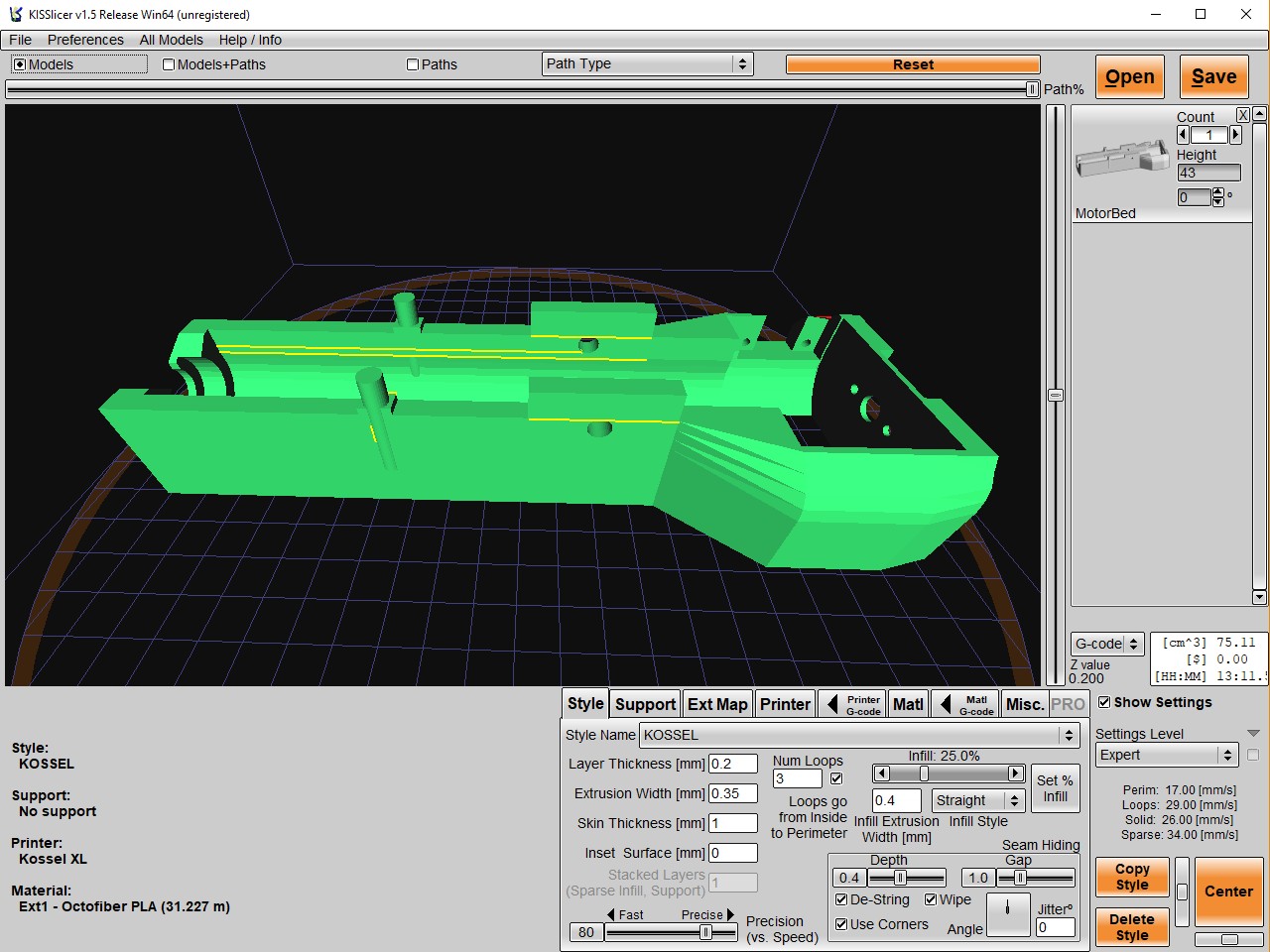
The next step was then to design the whole assembly, that would contain the motor, encoder, and the worm of the worm gear. I wanted to get it printed as a single part, so I had to limit the length of the part to around 20cm, to fit it onto my circular 25cm diameter printer bed. This was a little bit challenging, but I managed it by leaving the motor itself pretty much unsupported and hanging out at the end of the part. This way I could have a bearing at one end of the part (which i called "MotorBed"), and the motor attachment point at the other end, and have a slot for the encoder wheel, with screw holes to attach the encoder at the correct location. I also planned to have just the weight of the motor to press the wooden worm towards the large altitude gear, so I modeled some holes for bolts to attach this MotorBed to an U-shaped holder containing a couple of the bearings from the fidget spinners.
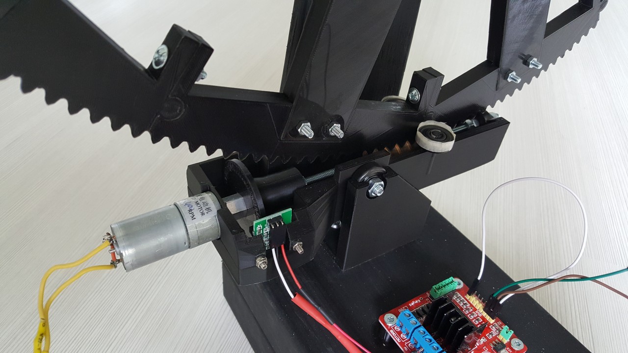
Aug 3rd, 2017 - First Altitude Control Tests!
After I had printed the MotorBed, I realized I had made an error when measuring the locations for the two bearings that keep the large gear at the center of the worm. Those bearings were a bit too far apart (better than they being too close, though!), so I just used some tape to increase their diameter slightly. It took so many hours to print the MotorBed, that I did not want to print it again just for this minor issue.
I also designed and printed the U-shaped holder for the MotorBed, and then started working on the wiring. I used the L298N Motor Driver from my original Piro robot to drive the altitude motor. I had read that it does not actually need all three wires (ENA, IN1 and IN2) to be controlled from the Raspberry Pi, it would be enough to control the IN1 and IN2 signals with PWM pulses, and connect the ENA signal directly to 5 volts, so that the motor is always enabled. As long as the IN1 and IN2 signals are both low, the motor will not run even if the ENA signal is high. This saves the number of wires (and GPIO pins) that are needed to drive the motors.
Finally today I had managed to do all the wiring needed for the altitude control, so it was time to start the system up, hoping for no magic smoke, and then writing some code to test the system. I managed to interface the motor controller and the encoders, so that when Stellarium sends a GoTo command, my code calculates the altitude angle, and attempts to drive the motors so that the number of on/off signal transitions received from the motor wheel encoder matches the difference in the altitude angle. I also realized that I can use just the level transition signal from the wheel encoder, so that both on-to-off and off-to-on generate a signal, and thus I could increase the resolution to 100 signals per full rotation, or 0.018 degrees.
Everything worked reasonably well, except that I noticed that the hole I drilled into the wooden screw is not at the exact center, despite my best efforts. This is probably not a big problem, especially if I still reduce the speed of the motor from the 200 rpm speeds I tested it with. Slewing the telescope some 10 or 20 degrees took only a second or two, so if I reduce the speed to 100 rpm or even slower, it still moves at a pretty good speed. I also need to add some ramp-up and ramp-down to the motor speed, so that it does not suddenly jerk to a new position.
Aug 6th, 2017 - Web Site Work
Yesterday I decided to create a web site for my PiKon Telescope project, so this weekend I have been working on getting this blog up to date, adding pictures, etc. I have not found all that much information on the net about the PiKon telescope, even though it was originally created back in 2014. I don't know why that is, as it seems to be quite a nice project for makers wanting to do something with a Raspberry Pi and 3D printing.
Next, I will need to start working on motorizing the azimuth axis. It would be nice if I could make that be able to run so slow that I could point it towards the North Star and convert my mount into an equatorial mount, but I'm not sure if that would be feasible. In any case I could have a bigger gear ratio for the azimuth angle, as the current gearing for the altitude angle is a bit too fast. It will still be a month or two before the night sky is dark enough to test some astrophotography, so I have that much time to work on the azimuth motor stuff. Too bad my summer vacation has ended, though, as that will make my progress much slower.
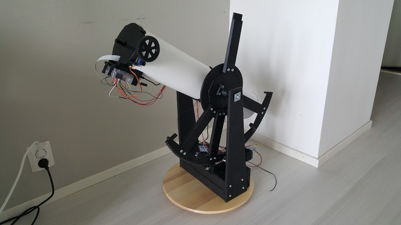
Here below is the most recent image of my PiKon Telescope. It is still pretty much a work in progress. That one altitude gear spoke that points upwards is for attaching some counterweight, to make the altitude worm not having to push against gravity when turning the axis.
Aug 8th, 2017 - STL Files Available
It occurred to me, that perhaps other people might be interested in modifying their PiKon telescope as well, so I added a section for the STL files I have used to my web pages. I did not include the parts for the motorized mount I am building, as those are created around the wooden screw I found, and thus would not be of use to anyone else. Feel free to use the included STL files in any way you see fit!
Aug 13th, 2017 - Base Design Work
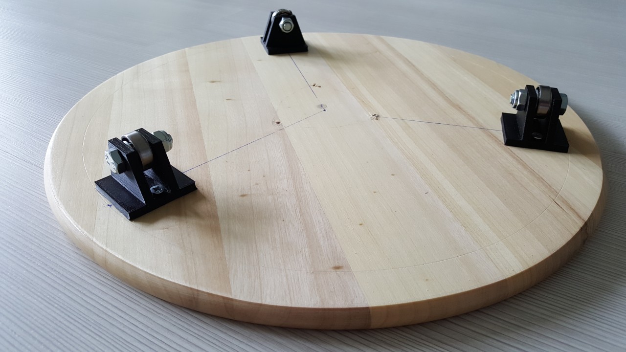
Since the last blog post I have been working on designing the azimuth (horizontal) rotation system. I had ordered a "Lazy Susan" SNUDDA turntable from IKEA as I thought I could use that pretty much as-is for the azimuth bearing. However, when it arrived, I noticed that it had a really poor quality bearing, and in addition to that, the rotational center was nowhere near the center point of the wooden tray! So, instead of using the original lazy susan bearing, I decided to go with three ceramic bearings rolling over a left-over storage cabinet shelf I had laying around. I 3D-printed some holdings for the bearings, and attached them to the bottom of the tray. In the picture below, you can see how far the original center point was from the actual center of the tray.
After attaching these bearings, I designed and printed an attachment for the center bearing around which the base will rotate. This middle bearing will keep this rotating part of the base attached to the bottom part of the base, while these three bearings will actually carry the weight of the telescope. Now I just needed to start printing the parts for the azimuth gear. I decided to go with a full 360 degrees rotation (even though I will probably only need around 180 degrees when using the telescope on my back yard), so I will need to print 10 of those 20-tooth gear sections, each of which takes around 5 hours to print.
Aug 25th, 2017 - Test Image of the Moon
This evening the Moon was visible in the evening sky (while the Sun was also still up). I still haven't had time to print and build all the azimuth gear parts, but I decided to check if I could find the Moon by manually pointing my telescope. I only managed to get one out-of-focus image before the Moon set behind the trees, and it took most of an hour to get even this one image.
I did learn a lot from this attempt, though.
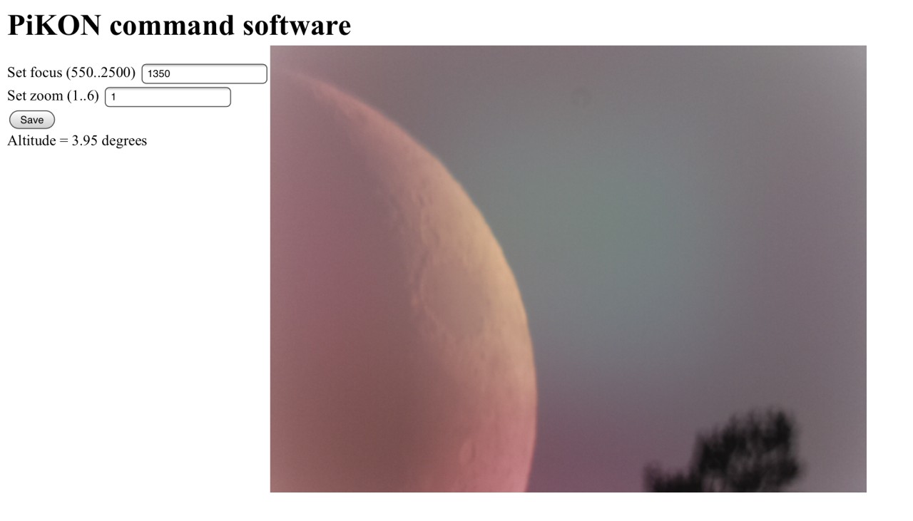
- The focus servo range seems to be sufficient for focusing to the Moon (and probably also to the stars). The range of the focus servo movement is from 550 to 2500, and the Moon was close to being in focus with the value of 1350. Before now I had only tried to focus to objects less than a kilometre away, so I was not sure how much the focus needs to change for objects much farther away.
- I need to be able to save an image from my "PiKON Command Software". Now I can use it only for changing the focus, and have to run to my computer, close down my software, and launch raspistill to take an actual image. This took so long, that the Moon had almost vanished from view before I managed to do all that!
- I need to have automatic refresh of the preview image in my software. Currently I need to refresh the page (or press the Save button) to see a new preview image.
- For some reason the first try to use Stellarium caused my releascope to pioint straight up, even though the Moon was near the horizon. Restarting my control software made it work correctly. I need to debug the cause for this behaviour.
- Obviously, I really need to get the motorized azimuth axis done. Even when I was able to use the Stellarium control to set the altitude angle correctly, it still took a lot of rotating the telescope around before I was able to find the Moon. And when I finally did, the altitude was no longer correct, so I had to use Stellarium again to adjust that, and then go back to adjusting the azimuth axis manually, and so on.
Aug 30th, 2017 - Software Work
As I noticed various shortcomings with my software when I tried to capture an image of the Moon, I have been working on my control software for a few days now. Firstly, I studied whether it would be possible to make the camera preview image go somwhere else besides the physical screen of the Raspberry Pi. If this is possible, then I could use the camera preview port for my preview image in my control software, and then use the actual still image port to save the images to the SD card. None of the the examples I had seen (mainly the raspistill and raspivid sources) had this possibility.
However, after some googling, I found a very promising software called PiKrellCam. It has the full source code in Github, so I was able to study how it uses the Raspberry Pi camera interface. Using that code as an example, I was able to create a system where the output from the camera preview port is resized (using the Raspberry Pi GPU hardware) to 640x480 and then stored into a ring buffer containing four images. Triple buffering would probably have worked just as well, but since I have no memory shortage I decided to go with four buffers. I used several buffers so that I don't need to lock the memory access when the web server code (running in a separate thread) fetches the latest preview image and sends it to the browser.
To have the preview image on my control software refreshed automatically, I added a Javascript snippet to my control software HTML page:
	<script>

	// Refresh the preview image once per second
	window.onload = function() {
	    var image = document.getElementById("preview");

	    function updateImage() {
	        image.src = image.src.split("?")[0] + "?" + new Date().getTime();
	    }

	    setInterval(updateImage, 1000);
	}

	</script>
This script refreshes the preview image once every second, as long as this web page is open in my browser. I also added a button to the page to call the image capture function of my software, which I adjusted to save a captured image to a time-stamped file, and then display this image in a separate browser tab.
When testing this new automatic refresh, I ran into a problem where it worked for a minute or two, but then my web server stopped sending the preview images. It took me a while to debug this problem, which eventually turned out to be a bug in the example code I had used when developing my multi-threaded web server. I had used the Simple Multi-threaded web server written in C using pthreads example from kturley.com for my web server, but that has a rather serious race condition in the thread launch code. The main routine gives a pointer to a local variable (holding the input socket ID) as a parameter to a thread it launches. If the browser sends several requests at a time, the main code launches several threads at the same time, and the main code variable value may change before the first thread starts running and reads the value! I fixed this by sending the socket ID itself to the thread, and not the address to the socket ID.
Sep 3rd, 2017 - Azimuth Axis Motor Holder Done
Today I managed to build the motor and worm gear holder for the azimuth axis. I used pretty much the same design as for the altitude axis, except that I replaced the plastic axles for the bearings that center the gear wheel with holes for bolts. I also moved the holes for the attach points towards the center of gravity, as this part will be mounted sideways and use a spring to keep it gripping the gear tightly.
Sep 9th, 2017 - Wiring Done!
Today I spent some time finishing up the wiring for the azimuth axis. Here below is the final wiring diagram for the Rapsberry Pi GPIO pins that I use (the background image is from the eLinux.org pages).
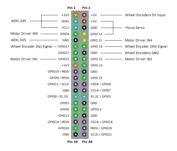
The ADXL345 accelerometer uses the I˛C headers. The focus servo uses the GPIO 14 header (I swapped the pins in the original servo connector, so that I could directly attach it to the Raspberry Pi header pins 4, 6 and 8). The wheel encoders take their power from pin 2 (using a splitter wire) and ground signal from pin 14 (again with a splitter wire), with the azimuth encoder signal (using a voltage divider circuit with 4.7kΩ and 10kΩ resistors) connected to GPIO 17, and the altitude signal similarly to GPIO 18.
The L298N motor driver has the ENA and ENB pins directly connected to it's 5V pin, so that I only need to connect the four IN pins to my Raspberry Pi. Those are connected to GPIO pins 22, 23, 4 and 15. Thus, I needed a total of 7 GPIO signal pins, with two input signals, one servo output, and four PWM output signals. Here below is the image of how the L298N motore driver is wired. Note the white wire that connects the ENA and ENB signals directly to the +5V output pin.

Sep 12th, 2017 - Video of the Stellarium Control
This weekend I managed get my telescope built up, including the azimuth axis motorization. I decided to create a video showcasing my control system. The weather was cloudy, so I did not take my telescope outside, I just tested the motion control without using my web sofware. I usually use the simple Windows Movie Maker to create my videos, but this time I wanted to have a picture-in-picture (or actually video-in-video) in my video, which is a feature that Movie Maker does not support. I had to revert back to my old video creation method of using AVISynth scripting and VirtualDub previewing. In order to create a modern H264 MP4 output video from AVISynth, which I can then edit in MovieMaker, I used Avidemux together with AVSProxy. I think the final result was satisfactory.
Now I just need to improve my software, and wait for some clear winter skies, to take some nice pictures with my telescope!
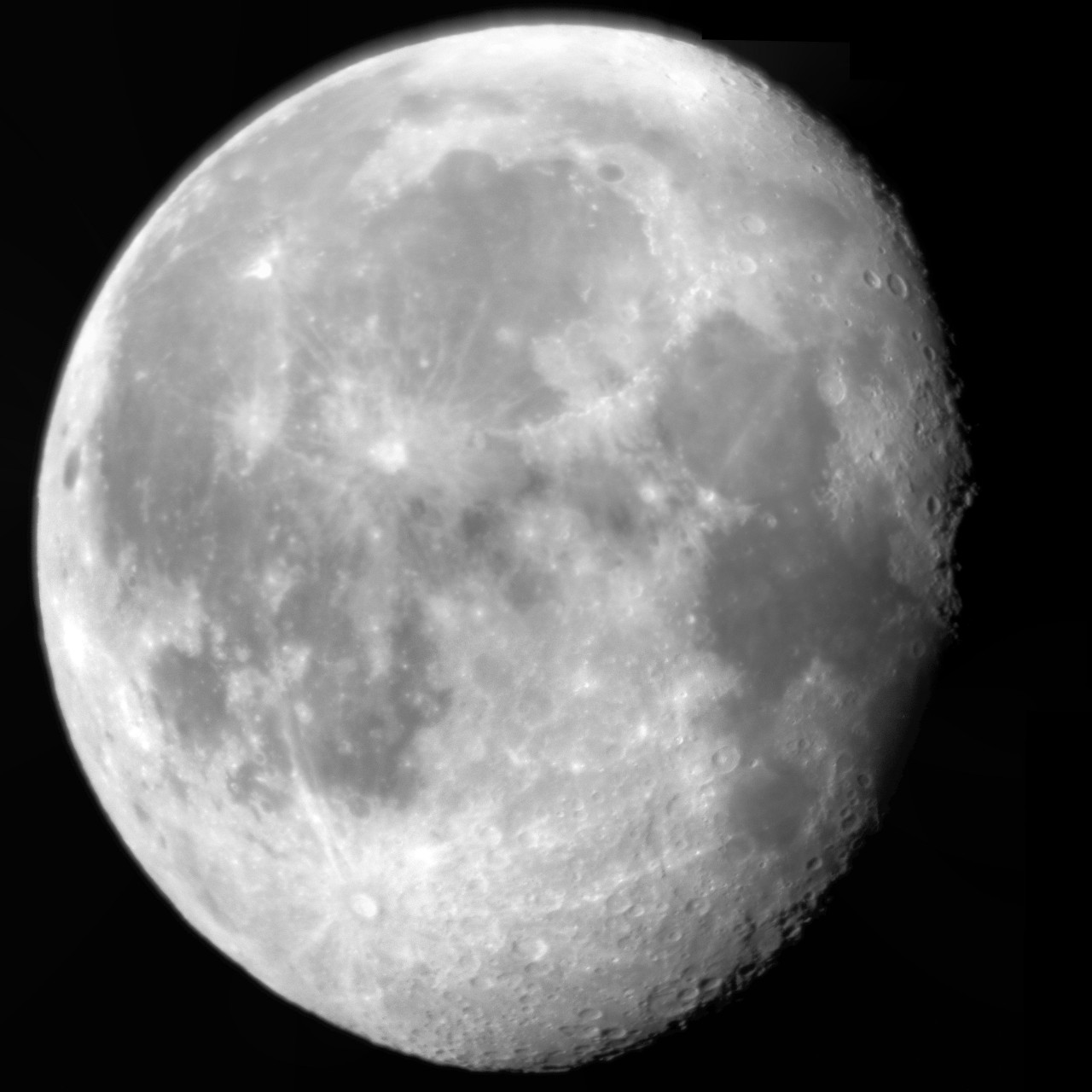
Nov 8th, 2017 - First pictures of the Moon!
Okay, yesterday finally there were some clear skies, and the moon was visible in the direction of the sky I can easily photograph using my telescope. I got up really early, around 4:00 in the morning, carried my telescope outside, and began calibrating the motorized mount. Pretty soon I managed to find the Moon, and began taking pictures. I took about 50 pictures, in an attempt to capture every part of the lunar surface (as the field of view of the telescope is such, that only about a quarter of a full moon fits into a single image). I also took some video, which I just uploaded to YouTube.
The composite image of the Moon below was created using IrfanView and Microsoft Image Composite Editor. I used IrfanView to convert the images to grayscale and adjust the brightness and contrast of each individual image, and then used the composite editor to generate the composite image. I had to do this in several steps, first the top half of the moon using several images where the top part of the Moon moved across the field of view, and then similarly with the bottom half. Finally I composited these halves together. The result was pretty good for such a first attempt using free software and pretty much every setting on automatic.